 1 / 2
1 / 2
Project Overview
Project Overview
The Wien Bridge Oscillator is a classic electronic circuit used to generate highly stable, low-frequency sine waves (typically in the audio frequency range). Unlike amplifiers that require an external input signal to produce an output, this oscillator generates its own continuous periodic waveform by utilizing positive feedback and a specific frequency-selective RC network.
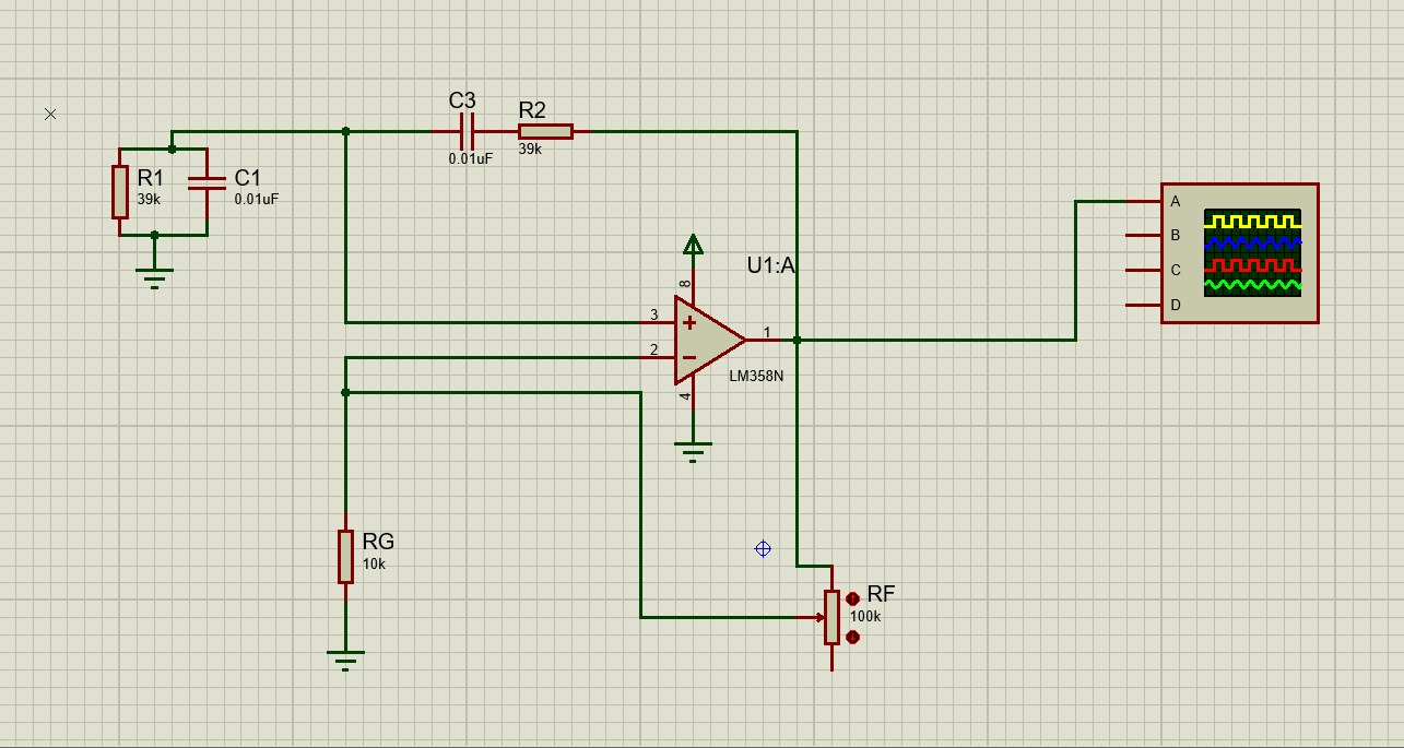
This project demonstrates the complete design, theoretical calculation, and virtual simulation of a Wien Bridge Oscillator using the widely available LM358 operational amplifier within the Proteus Design Suite.
Component Breakdown
- LM358N Operational Amplifier (U1:A): The active element providing the necessary voltage gain to sustain oscillations.
- Frequency Network Resistors (R1, R2): 39kΩ standard resistors.
- Frequency Network Capacitors (C1, C3): 0.01µF ceramic capacitors.
- Gain Setting Resistor (RG): 10kΩ fixed resistor.
- Feedback Potentiometer (RF): 100kΩ variable resistor used for fine-tuning the amplifier's gain.
- Virtual Instruments: Proteus Digital Oscilloscope for real-time waveform analysis.
Circuit Architecture & Working Principle
For an oscillator to function, it must satisfy the Barkhausen Criterion: the total phase shift around the loop must be 0° (or 360°), and the loop gain must be equal to or slightly greater than 1.
1. The Lead-Lag Network (Positive Feedback)
The core of the Wien Bridge is the RC network connected to the non-inverting input (Pin 3) of the op-amp. It consists of a series RC circuit (R2, C3) and a parallel RC circuit (R1, C1).
At a very specific resonant frequency, the phase shift through this network is exactly 0°, and the signal attenuation is precisely 1/3. This frequency is determined by the formula:
f = 1 / (2 × π × R × C)
2. The Amplifier Stage (Negative Feedback)
Because the lead-lag network attenuates the signal by a factor of 3, the op-amp must provide a voltage gain of exactly 3 to maintain a loop gain of 1. The op-amp is set up in a non-inverting configuration. Its gain is determined by the formula:
Gain (A) = 1 + (RF / RG)
To achieve a gain of 3, the ratio of RF to RG must be 2. In this circuit, RG is 10kΩ, meaning RF needs to be tuned to approximately 20kΩ using the 100kΩ potentiometer.
Simulation & Testing Methodology
The circuit was simulated using Proteus 8 Professional. The testing process involved:
- Wiring the schematic as per standard Wien Bridge topology.
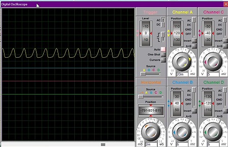
- Connecting Channel A of the digital oscilloscope to the output pin (Pin 1) of the LM358 to monitor the generated signal.
- Initiating the simulation and carefully adjusting the 100kΩ potentiometer (RF).
- If the gain is too low (Gain < 3), oscillations will decay and stop.
- If the gain is too high (Gain > 3), the sine wave will clip and distort into a square-like wave.
- Fine-tuning RF until a perfectly sustained, undistorted continuous waveform was achieved on the oscilloscope screen, proving the successful operation of the oscillator.
Applications
Wien Bridge Oscillators are widely used in audio testing equipment, function generators, and any application requiring a pure, low-distortion sine wave at low to medium frequencies.
Tech Stack
Tags
| Op-Amp | LM358N |
| Resistors (Bridge) | 39kΩ (R1, R2) |
| Capacitors (Bridge) | 0.01µF (C1, C3) |
| Gain Resistor | 10kΩ (RG) |
| Feedback Potentiometer | 100kΩ (RF) |
| Theoretical Frequency | ~408 Hz |
| Simulation Software | Proteus 8 Professional |