 1 / 4
1 / 4
Project Overview
Project Objective
To design, simulate, and implement a high-precision 2-digit digital counter architectural system capable of tracking synchronous sequences from 00 to 99. The control loop utilizes a modular cascading logic setup, advancing dynamically with manual pulse inputs and auto-resetting upon reaching peak boundary thresholds.
Integrated Hardware Infrastructure
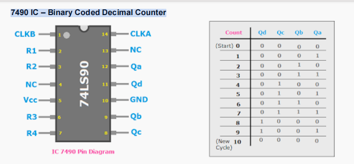
- Generates structured 4-bit Binary Coded Decimal (BCD) tracking arrays.
- Cycles seamlessly through 10 deterministic states (0000 to 1001).
- Supports multi-stage cascading arrays to scale number boundaries.
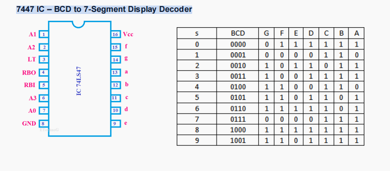
- Translates raw 4-bit configurations into distinct visual control maps.
- Engineered with Active-LOW outputs ideal for Common-Anode arrays.
- Features dedicated Lamp Test (LT) and Blanking Input (BI) controls.
- Arranged high-efficiency LED segment profiles rendering digits 0-9.
- Shared central anode rail power distribution paths.
- Equipped with dedicated series resistors targeting 12-20 mA current safety.
- Manual tactile push-button switch generating clean clock steps.
- Flexible pull-up/pull-down resistor profiles to tune edge transitions.
- Triggers immediate value progression on precise press/release parameters.
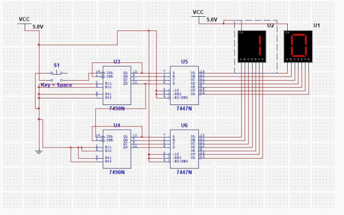
Circuit Functionality & Execution Logic
The execution framework isolates processing loads between two dedicated stages: the first 7490 IC handles the continuous **units place computation**, while the second tracks the **tens place calculations**.
System Architecture Parameters
| Parameter / Vector Node | Target Specifications | Operational Deployment Status |
|---|---|---|
| Counting Boundary Matrix | 00 to 99 Base Decimal | Auto-Reset Verified |
| Logic Encoding Formats | 4-Bit Binary Coded Decimal (BCD) | State Sequence (0000 - 1001) |
| Display Hardware Mapping | Common-Anode 7-Segment Array | Active-LOW Segment Activation |
| Target Segment Current Load | 12 mA to 20 mA Max Variance | Resistor Limited |
| Expandability Rating | Modular Cascade Capable | Up to 3-Digit (999) Node Ready |
Simulation Portfolio Verification
Proteus EDA modeling validated complete execution trace pathways. Waveform analyses confirmed clean propagation delay metrics across cascading clock intersections, maintaining solid 5V logic thresholds without voltage droop during multiple segment toggles.
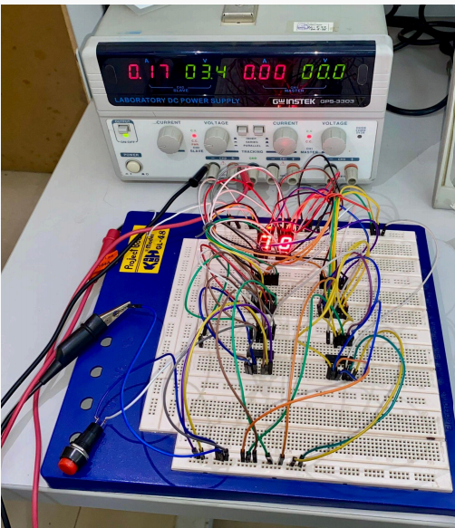
Physical Hardware Design Layout
The structural hardware prototype maps logic ICs closely together on a unified bus standard to minimize trace capacitance. Dedicated in-line resistor networks are placed adjacent to display leads, optimizing physical footprint and securing heat dissipation targets.
Conclusion
This project successfully demonstrates the construction of a reliable, high-readability 2-digit digital counter system. By leveraging standard 7490 decade chips, 7447 decoder units, and common-anode hardware arrays, the implementation delivers clear real-time visual tracking data. The fully modular design ensures structural agility, making it easily adaptable for real-world automation, assembly lines, and digital instrumentation applications.
Tech Stack
Tags
| Counter IC | 7490 Decade Counter (x2) |
| Decoder IC | 7447 BCD-to-7-Segment (x2) |
| Display Type | Common-Anode 7-Segment (x2) |
| Operating Voltage | 5V DC (TTL Standard) |
| Current Per Segment | 12mA - 20mA |
| Input Trigger | Tactile Push-Button Switch |
| Simulation Software | Proteus EDA |