 1 / 3
1 / 3
Project Overview
Project Objectives
To design and implement a microcontroller-based system for operating a DC motor with varying and constant speeds based on defined patterns and timing requirements. The task simulates an industrial application where motor speed control is crucial.
Problem Description & Speed Profiles
The execution framework is explicitly tuned to safely accelerate, maintain, and modulate the DC motor lifecycle following two distinct algorithmic sequence layouts:
- Gradually scales working velocity to absolute limits over a runtime duration of 1.5 minutes.
- Smoothly dampens velocity downward back to zero limits within the matching subsequent 1.5 minutes.
- Formally commands a complete structural motor power OFF cycle state.
- Deploys operational power at low baseline threshold rates for an initial 30-second window.
- Applies multiplier layers to systematically double the running speeds for the next 30 seconds.
- Applies additional operational multiplication vectors again for the subsequent 30 seconds.
- Initiates uniform deceleration down steps following identical symmetric temporal delays.
- Gracefully turns OFF active system power distribution structures.
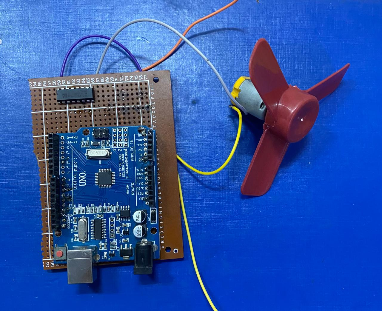
System Infrastructure
Circuit Interconnection Matrix
| Arduino Microcontroller Pin | Motor Driver Terminal Link | Functional Allocation Assignment |
|---|---|---|
| D9 (ENA) | ENA | PWM Target Output Signals for Real-Time Velocity Changes |
| D13 (IN1) | IN1 | Motor Direction Matrix Configuration Alpha State Mapping |
| D12 (IN2) | IN2 | Motor Direction Matrix Configuration Beta State Mapping |
| GND | GND | Common Ground Interface System Unification Plane |
| 5V | Vcc (Logic Power) | Optional Logic Core Operational Power Support Line |
Automation Source Code Implementation
C++ / Arduino// Arduino Control Framework for Industrial DC Motor Scaling
const int ENA = 9; // PWM terminal mapping for real-time velocity scales
const int IN1 = 13; // Matrix direction register assignment channel A
const int IN2 = 12; // Matrix direction register assignment channel B
// Setup baseline velocity profiles (Quantized 8-Bit Resolution limits)
const int speed1 = 50; // Minimum functional cutoff value to counteract static friction
const int speed2 = 255; // Peak duty-cycle saturation velocity limit
void setup() {
// Configure direction hardware state profiles
pinMode(ENA, OUTPUT);
pinMode(IN1, OUTPUT);
pinMode(IN2, OUTPUT);
// Establish default system rotation heading rules (Forward Loop Vector)
digitalWrite(IN1, HIGH);
digitalWrite(IN2, LOW);
// Mount tracking connection channels
Serial.begin(9600);
}
void loop() {
Serial.println("Executing Speed Profile Pattern 1...");
Pattern1();
delay(5000); // Standard layout system stabilization pause
Serial.println("Executing Speed Profile Pattern 2...");
Pattern2();
delay(5000); // Cyclical cooldown break window tracking
}
// Print tracking metrics and adjust power outputs
void printSpeed(int speed) {
analogWrite(ENA, speed);
Serial.print("Speed registry values updated to: ");
Serial.print(speed);
Serial.print(" | Active Allocation Level: ");
Serial.print(map(speed, 0, 255, 0, 100));
Serial.println("%");
}
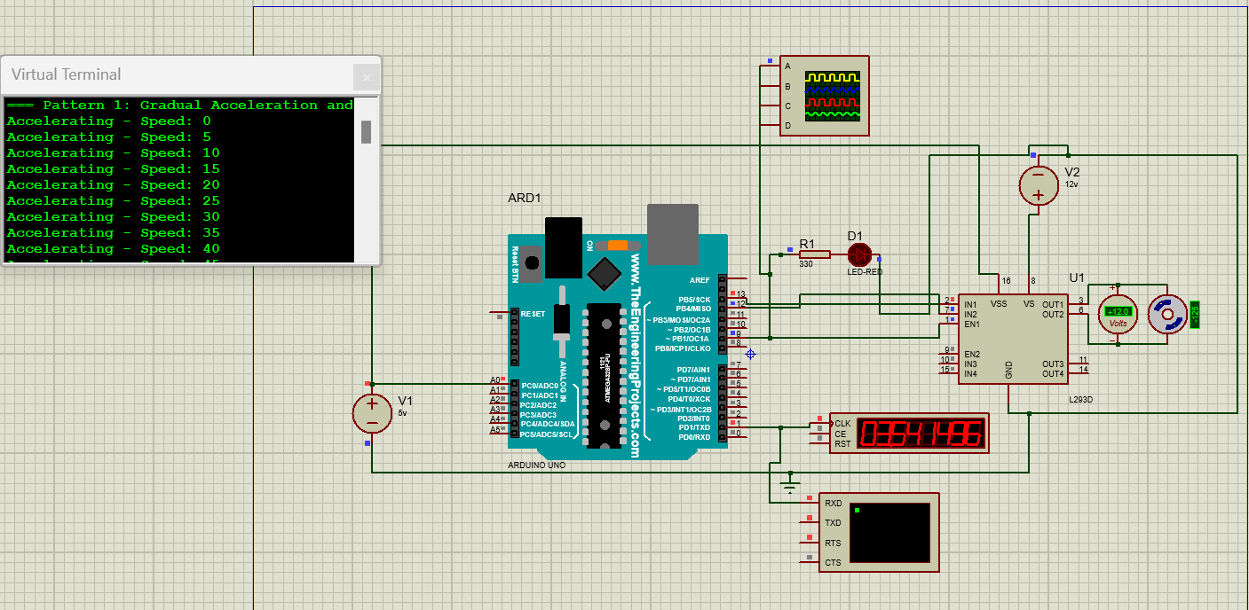
// Pattern 1 Strategy: Linear Acceleration & Deceleration Ramp Slopes
void Pattern1() {
const unsigned long rtime = 90000; // 1.5 Minutes parsed into milliseconds
const int steps = 100; // Incremental execution tracking steps
// Continuous acceleration ramp slope execution
for (int i = 0; i <= steps; i++) {
int speed = map(i, 0, steps, speed1, speed2);
printSpeed(speed);
delay(rtime / steps);
}
// Continuous deceleration ramp slope execution
for (int i = steps; i >= 0; i--) {
int speed = map(i, 0, steps, speed1, speed2);
printSpeed(speed);
delay(rtime / steps);
}
// Complete system actuator isolation safety process
printSpeed(0);
Serial.println("System Isolation Active: Motor Standby Status OK.");
}
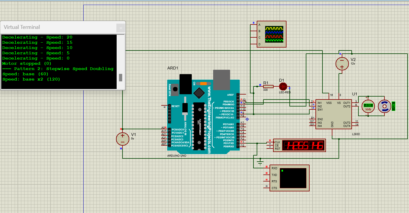
// Pattern 2 Strategy: Segmented Step Profile Multipliers
void Pattern2() {
const unsigned long sTime = 30000; // 30-Second operational block windows
int baseSpeed = 60; // Low starting baseline velocity parameter
// Sequential level mapping configuration array
int speedLevels[] = {baseSpeed, baseSpeed*2, baseSpeed*4, baseSpeed*2, baseSpeed, 0};
for (int i = 0; i < 6; i++) {
printSpeed(speedLevels[i]);
Serial.print("Sequence Matrix Step [");
Serial.print(i+1);
Serial.print("] Active - Operational Velocity Node: ");
Serial.println(speedLevels[i]);
delay(sTime);
}
Serial.println("System Isolation Active: Motor Standby Status OK.");
}Challenges & Engineering Considerations
- Timing Precision Matrix: Handled using simple software loop blocking functions via native
delay()rules; this can scale seamlessly to non-blockingmillis()structures for asynchronous operations. - Pulse-Width Modulation Stability: Internal Arduino control nodes efficiently output accurate signal adjustments using underlying processor timer parameters managed by structural calls to
analogWrite(). - Voltage Isolations & Thresholds: The mechanical unit relies on an independent high-power 12V operational supply rail, while the delicate controller runs on standard 5V logic parameters to eliminate inductive noise.
- Simulation Testing & Verification: Circuit design models were completely mapped, debugged, and virtually validated inside the Proteus environment engine before deploying to prototype test configurations.
Engineering Project Summary
The designed microcontroller system successfully achieves the required motor control patterns with appropriate speed variations and time delays. The hardware and software integration was tested through simulation and confirmed operational accuracy. This project showcases practical embedded system design for motor automation environments.
Tech Stack
Tags
| Microcontroller | Arduino Uno (ATmega328P) |
| Motor Driver | L293N Dual H-Bridge |
| Motor Type | 12V Brushed DC Motor |
| Motor Current | 0.3A |
| Motor Voltage | 12V DC |
| Control Method | PWM Speed Control |
| PWM Resolution | 8-bit (0-255) |
| PWM Output Pin | D9 |
| Direction Control Pins | D12, D13 |
| Operating Voltage | 5V DC |
| Power Supply | 12V DC |
| Clock Frequency | 16 MHz |
| Communication | UART Serial (9600 bps) |
| Software | Arduino IDE |
| Simulation | Proteus 8 Professional |
| Control Algorithm | Open-Loop Speed Control |
| Pattern 1 Duration | 180 Seconds |
| Pattern 2 Duration | 150 Seconds |
| PWM Frequency | 490 Hz |
| Grounding | Common Ground Configuration |