 1 / 5
1 / 5
Project Overview
Proteus Simulation · Electronics Project
Auto Cutoff
Battery Charger
A relay-controlled smart charger that automatically stops charging the moment your battery hits its target voltage — built around the LM358 op-amp comparator and verified in Proteus.
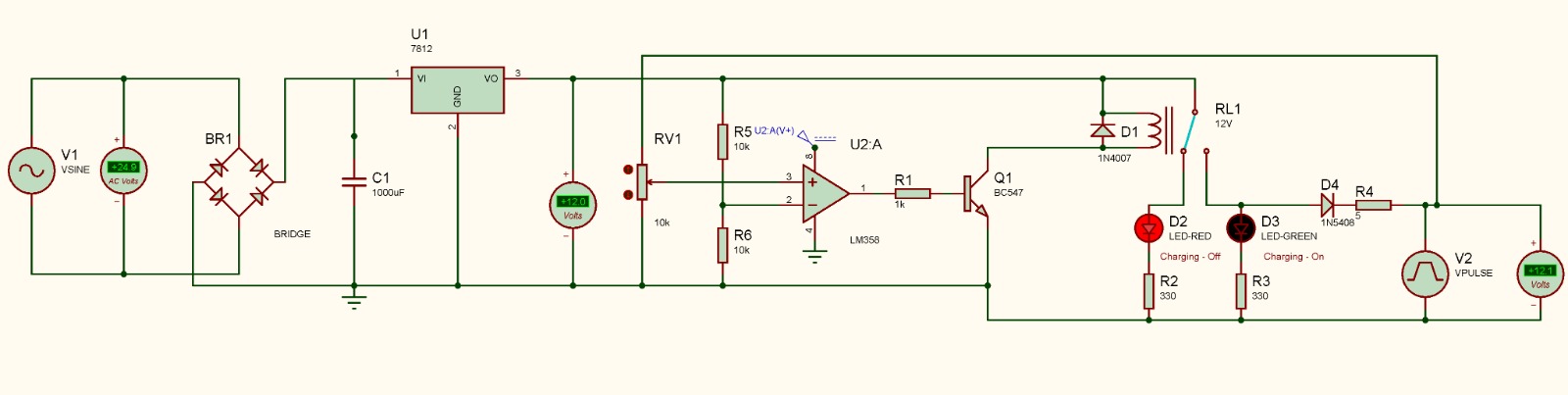
State A — Active
🟢 Charging ON
Relay RL1 energised — Q1 saturated — Green LED (D3) lit — current flowing to battery
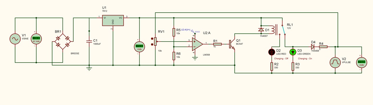
State B — Cutoff
🔴 Charging OFF
Relay RL1 open — Q1 cut off — Red LED (D2) lit — battery at target voltage
Circuit Analysis
How it works —
stage by stage
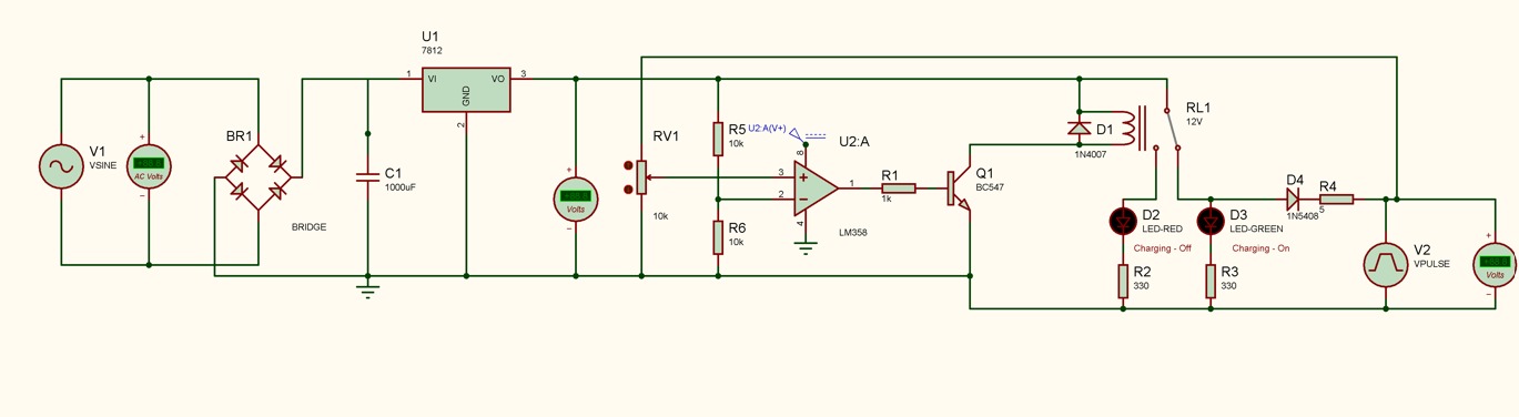
Seven cascaded stages convert raw AC mains into a smart self-terminating charging system.
01
AC Input & Rectification
V1 (VSINE) → BR1 (Bridge Rectifier) → C1 (1000µF Filter Cap)
- V1 provides the AC mains simulation — 35V peak sinusoidal at 50Hz
- BR1 is a full-wave bridge rectifier converting AC to pulsating DC
- C1 (1000µF) smooths ripple into clean DC ready for the regulator
02
Voltage Regulation — LM7812
Rectified DC → U1 (LM7812) → +12V Stable Rail
- U1 (LM7812) is a 3-terminal linear regulator — rock-solid +12V output
- Powers the comparator stage, relay coil, and LED indicators
- The voltmeter probe confirms the regulated 12V rail in simulation
03
Voltage Sensing & Comparison — LM358 (The Brain)
Battery → R5/R6 divider → LM358 pin 2 (−) | RV1 → LM358 pin 3 (+)
- RV1 sets the cutoff threshold on the non-inverting input (pin 3 +)
- R5 + R6 (10kΩ each) form a voltage divider sampling battery voltage into pin 2 −
- Battery < setpoint → output HIGH → transistor ON → relay ON → charging
- Battery ≥ setpoint → output LOW → transistor OFF → relay OFF → cutoff
04
Transistor Switch — BC547
LM358 output → R1 (1kΩ) → Q1 (BC547 NPN) Base
- R1 (1kΩ) limits base drive current into Q1 safely
- Q1 saturated (comparator HIGH) → drives relay coil current
- Q1 cut off (comparator LOW) → relay coil de-energised → open circuit
05
Relay & Flyback Protection — RL1 + D1
Q1 Collector → RL1 Coil (12V) ‖ D1 (1N4007 flyback)
- RL1 is a 12V SPDT relay — physically connects/disconnects the charging path
- D1 (1N4007) clamps inductive voltage spikes when the coil switches off — mandatory protection for Q1
06
LED Status Indicators — D2 & D3
Relay NO/NC → D2 (Red) + D3 (Green) via R2/R3 (330Ω)
- D3 Green — "Charging On" — lights when relay is closed and current flows
- D2 Red — "Charging Off / Full" — lights when relay opens at cutoff
- R2 & R3 (330Ω) limit LED current to a safe level
07
Battery / Load Simulation — VPULSE
V2 (VPULSE) → D4 (1N5408) → Load / Battery
- V2 ramps from 8V (discharged) to 12.1V (fully charged) over 8 seconds
- When it crosses the RV1 threshold, the LM358 flips and triggers cutoff
- D4 (1N5408) blocks reverse current from the battery back into the charger
- R4 provides a small series resistance for the simulation current path
Proteus Setup
Simulation source
configurations
Exact Proteus component settings used for both voltage sources.
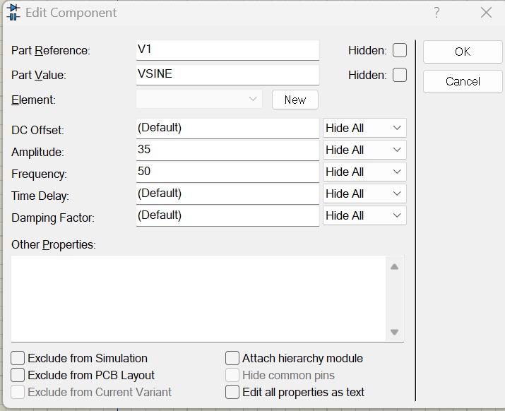
V1 — VSINE
AC Mains Simulation
DC OffsetDefault (0V)
Amplitude35V peak
Frequency50 Hz
Time DelayDefault
DampingDefault
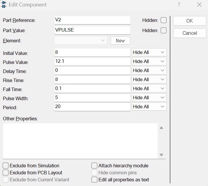
V2 — VPULSE
Battery Voltage Simulation
Initial Value8V (dead battery)
Pulse Value12.1V (fully charged)
Delay Time0s
Rise Time8s (slow ramp)
Fall Time0.1s
Pulse Width5s
Period20s
Why 35V peak? After full-wave rectification and filtering, the peak is approximately 35V − 1.4V (bridge diode drops) = 33.6V. The LM7812 clamps this cleanly to a stable +12V output rail. The VPULSE ramps from 8V → 12.1V over 8 seconds, crossing the comparator threshold mid-simulation so you can observe the complete charge → cutoff transition in a single transient run.
Comparator logic
LM358 U2:A decision table — pin 3 is RV1 reference, pin 2 is battery sense.
| Battery voltage vs RV1 | LM358 output | Q1 state | Relay RL1 | LED status |
|---|---|---|---|---|
| Battery < threshold | HIGH | Saturated | Energised (closed) | 🟢 Green ON |
| Battery ≥ threshold | LOW | Cut off | De-energised (open) | 🔴 Red ON |
Bill of Materials
Every component,
listed and explained
| Ref | Component | Value / Part | Function |
|---|---|---|---|
| V1 | AC Source | VSINE, 35V pk, 50Hz | Mains simulation |
| V2 | Pulse Source | VPULSE, 8→12.1V | Battery voltage simulation |
| BR1 | Bridge Rectifier | BRIDGE | Full-wave rectification |
| C1 | Electrolytic Cap | 1000µF | Ripple filtering |
| U1 | Voltage Regulator | LM7812 | +12V regulated rail |
| U2:A | Op-Amp | LM358 | Voltage comparator (the brain) |
| RV1 | Potentiometer | 10kΩ | Cutoff voltage setpoint — adjustable |
| R1 | Resistor | 1kΩ | Q1 base current limiter |
| R2 | Resistor | 330Ω | Red LED current limiter |
| R3 | Resistor | 330Ω | Green LED current limiter |
| R4 | Resistor | (sim) | Series simulation load resistance |
| R5 | Resistor | 10kΩ | Voltage divider — upper arm |
| R6 | Resistor | 10kΩ | Voltage divider — lower arm |
| Q1 | NPN Transistor | BC547 | Relay driver switch (100mA Ic) |
| RL1 | Relay | 12V SPDT coil | Charging path physical switch |
| D1 | Rectifier Diode | 1N4007 | Relay flyback / freewheel protection |
| D2 | LED — Red | LED-RED | "Charging Off / Full" indicator |
| D3 | LED — Green | LED-GREEN | "Charging On" indicator |
| D4 | Rectifier Diode | 1N5408 | Reverse current block (high current rated) |
Design Notes
Protections, tips
& calibration
Flyback diode D1 is mandatory
When the relay coil de-energises, it produces a large inductive voltage spike in reverse polarity. Without D1 (1N4007) clamping it, Q1 (BC547) will be destroyed on the very first cutoff event.
D4 handles real current
The 1N5408 is rated significantly higher than normal signal diodes (3A continuous forward current), offering crucial low forward drop and preventing the battery from back-powering the regulator array when the mains power shuts off.
Tech Stack
Proteus Design Suite
KiCad
LM358
LM7812
BC547
1N4007
1N5408
SPICE Simulation
Bridge Rectifier
LM358 Op-Amp
Tags
Technical Specs
| AC Input Voltage | 35V peak (VSINE, 50Hz) |
| Regulated DC Output | +12V (LM7812) |
| Filter Capacitor | 1000µF electrolytic |
| Cutoff Voltage | Adjustable via RV1 (10kΩ potentiometer) |
| Comparator IC | LM358 op-amp (U2:A), single-supply |
| Transistor Switch | BC547 NPN (Q1), 100mA Ic max |
| Base Resistor | R1 = 1kΩ |
| Relay | RL1 12V SPDT |
| Flyback Protection Diode | D1 — 1N4007 |
| Output Reverse-Block Diode | D4 — 1N5408 |
| Voltage Divider | R5 = R6 = 10kΩ |
| LED Current-Limit Resistors | R2 = R3 = 330Ω |
| Green LED (D3) | Charging active indicator |
| Red LED (D2) | Charging complete / cutoff indicator |
| Battery Sim Source (V2) | VPULSE 8V → 12.1V, rise 8s, period 20s |
| Simulation Platform | Proteus Design Suite |