GenxiTechSolutions

How Does a Non-Inverting Amplifier Work? Gain and Offset Example (30mV to 3.3V)
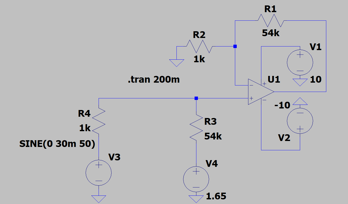
LTspice schematic of a non-inverting amplifier with 55k and 1k resistors, a 1.65V reference input, and a 30mV sine source

A non-inverting amplifier is one of the most common op-amp circuits used to boost a signal's voltage without flipping its polarity — meaning the output waveform stays perfectly in phase with the input. In this article, we'll break down how it works, derive the gain formula, and walk through a real simulation in LTspice where a 30mV signal is amplified to 3.3V with a 1.65V DC offset added on top.

What Is a Non-Inverting Amplifier?

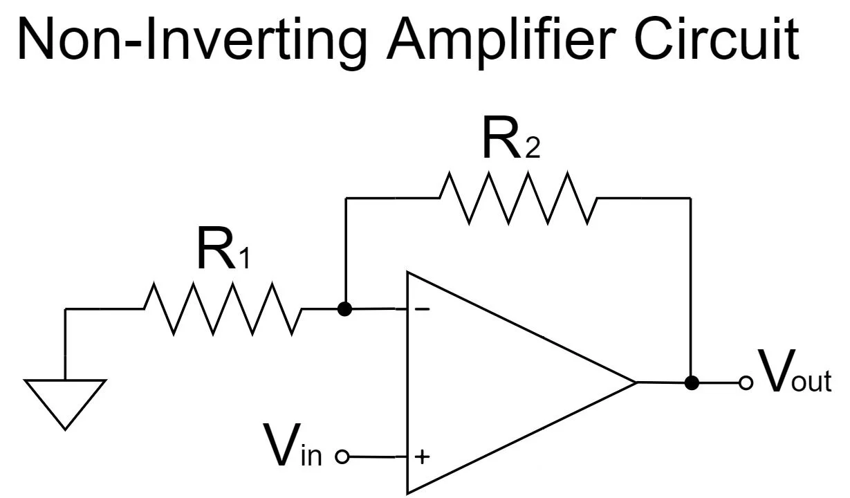
In a non-inverting amplifier, the input signal is applied directly to the op-amp's non-inverting (+) terminal, while a voltage divider made of two resistors (R1 and R2) feeds a portion of the output back into the inverting (-) terminal. This creates negative feedback, which stabilizes the gain and keeps the output in phase with the input.

This circuit adds one more part. A second pair of resistors (R3 and R4) brings a fixed reference voltage into the same non-inverting terminal as the signal. That reference is what lets the output sit on a new DC center instead of staying at 0V.
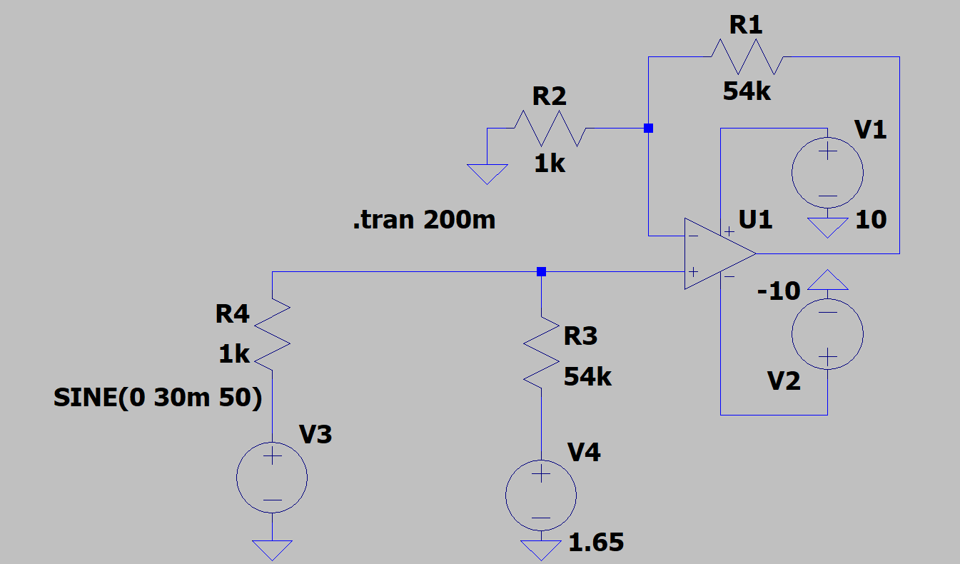
LTspice schematic of a non-inverting amplifier with 55k and 1k resistors, a 1.65V reference input, and a 30mV sine source
LTspice schematic: non-inverting amplifier with R1 = 55k, R2 = 1k, R3 = 55k, R4 = 1k, reference V4 = 1.65V, and a ±10V dual supply.

The Gain Formula

The closed-loop gain of this non-inverting amplifier is given by:

Av = R1 / R2

Where:

  • R1 is the feedback resistor (connected between the output and the inverting input)
  • R2 is the resistor connected between the inverting input and ground

This formula only holds if R3/R4 is set to the same ratio as R1/R2.

Why This Formula Has No Plus One

Our other article on the plain non-inverting amplifier uses Av = 1 + (R2/R1). That plus one shows up because the non-inverting terminal there carries Vin and nothing else.

This circuit is wired differently. The non-inverting terminal here carries a mix of Vin and Vref, blended together by R3 and R4. Once you work through the node equations for both op-amp inputs and set them equal, that plus one term cancels out of the signal path. What is left is a simpler relationship where Vin is scaled by R1/R2 alone, and Vref is added separately as the offset:

Vout = Vref + (R1/R2) × Vin

Same op-amp, same negative feedback idea, but a different formula because the non-inverting terminal is wired differently.

Worked Example: 30mV In, 3.3V Out

Using the LTspice circuit above, R1 = 55kΩ and R2 = 1kΩ. Plugging these into the formula:

Av = 55k / 1k = 55

The input source is a 30mV peak sine wave at 50Hz with no DC offset — SINE(0 30m 50). Since the gain is 55, the output swing becomes:

Vout swing = Av × Vin = 55 × 30mV = 1.65V peak

The reference voltage V4 = 1.65V sets where that swing sits, giving the full equation:

Vout = 1.65V + 55 × Vin

The op-amp is powered from a ±10V dual supply (V1 = +10V, V2 = -10V), which gives enough headroom so the 3.3V peak output never clips against the rails.
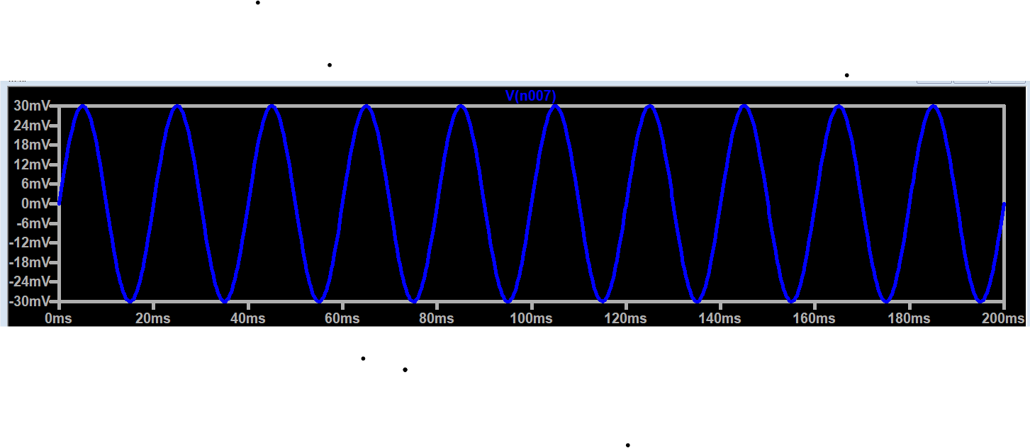
LTspice simulation waveform showing the 30mV input sine wave centered at 15mV
Input signal: 50Hz sine wave, swinging from 0mV to 30mV, centered at 15mV.
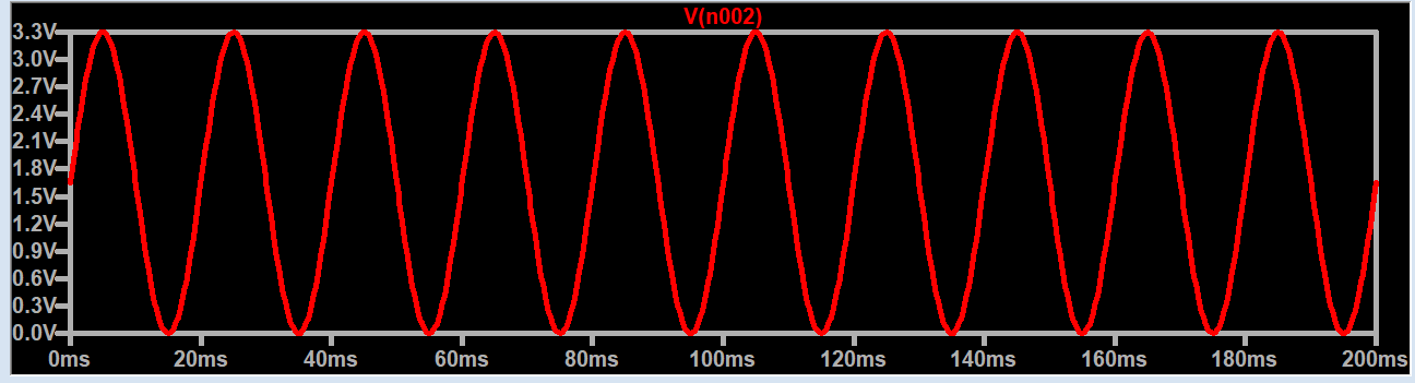
LTspice simulation waveform showing the amplified output sine wave centered at 1.65V
Output signal: same 50Hz sine wave, now swinging from 0V to 3.3V, centered at 1.65V.

Why There's a DC Offset This Time

In the plain non-inverting amplifier, R2 connects straight to ground and the output stays centered at 0V. Here, R4 connects to a 1.65V reference instead of ground, and R3 matches R1. That reference voltage passes through the same gain as the signal, so it appears at the output as a steady 1.65V center. Change V4 and the output's center moves with it, the gain stays at 55 the whole time.

Key Takeaways

  • Non-inverting amplifiers keep the output in phase with the input.
  • Gain here is R1/R2, with no plus one, because the non-inverting terminal carries a mix of Vin and Vref rather than Vin alone.
  • R3 and R4 add a DC offset without changing the gain, as long as R3/R4 matches R1/R2.
  • A dual supply (±10V here) gives the output room to swing between 0V and 3.3V without clipping.
Frequently Asked Questions

What is a non-inverting amplifier?

An op-amp circuit where the input signal connects to the non-inverting (+) terminal, producing an output that is in phase with the input and amplified by a fixed gain.

What is the gain formula for this non-inverting amplifier?

Av = R1/R2, where R1 is the feedback resistor and R2 connects the inverting input to ground.

Why doesn't this formula have a plus one like the standard non-inverting amplifier?

The plus one comes from the non-inverting terminal carrying only Vin. Here that terminal carries a mix of Vin and Vref through R3 and R4, and that mix cancels the plus one out of the signal gain.

How does this circuit add a DC offset?

R3 and R4 bring a fixed reference voltage into the non-inverting input. As long as R3/R4 matches R1/R2, that reference becomes the output's offset, giving the full equation Vout = Vref + (R1/R2) × Vin.

Why is the gain 55 in this example?

The output needs to swing 1.65V (half of the 3.3V range) for every 30mV of input swing. 1.65V divided by 30mV equals 55.

Why use a dual supply like ±10V?

A dual supply gives the op-amp enough voltage headroom above and below the 0 to 3.3V output range so the signal never clips against the power rails.

Frequently Asked Questions

An op-amp circuit where the input signal connects to the non-inverting (+) terminal, producing an output that is in phase with the input and amplified by a fixed gain.

Gain (Av) = R1/R2, where R1 is the feedback resistor and R2 connects the inverting input to ground.

A second resistor pair, R3 and R4, carries a fixed reference voltage into the non-inverting input alongside the signal. As long as R3/R4 matches R1/R2, that reference appears at the output as a clean DC offset.

The output needs to swing 1.65V (half of the 3.3V range) for every 30mV of input swing. 1.65V divided by 30mV equals 55, so R1/R2 is set to that ratio.

A dual supply gives the op-amp enough voltage headroom above and below the 0 to 3.3V output range so the signal never clips against the power rails.

Related Topics

🤖

GenxiTech Assistant

Online · AI Powered · Always Ready