How Does a Non-Inverting Amplifier Work?
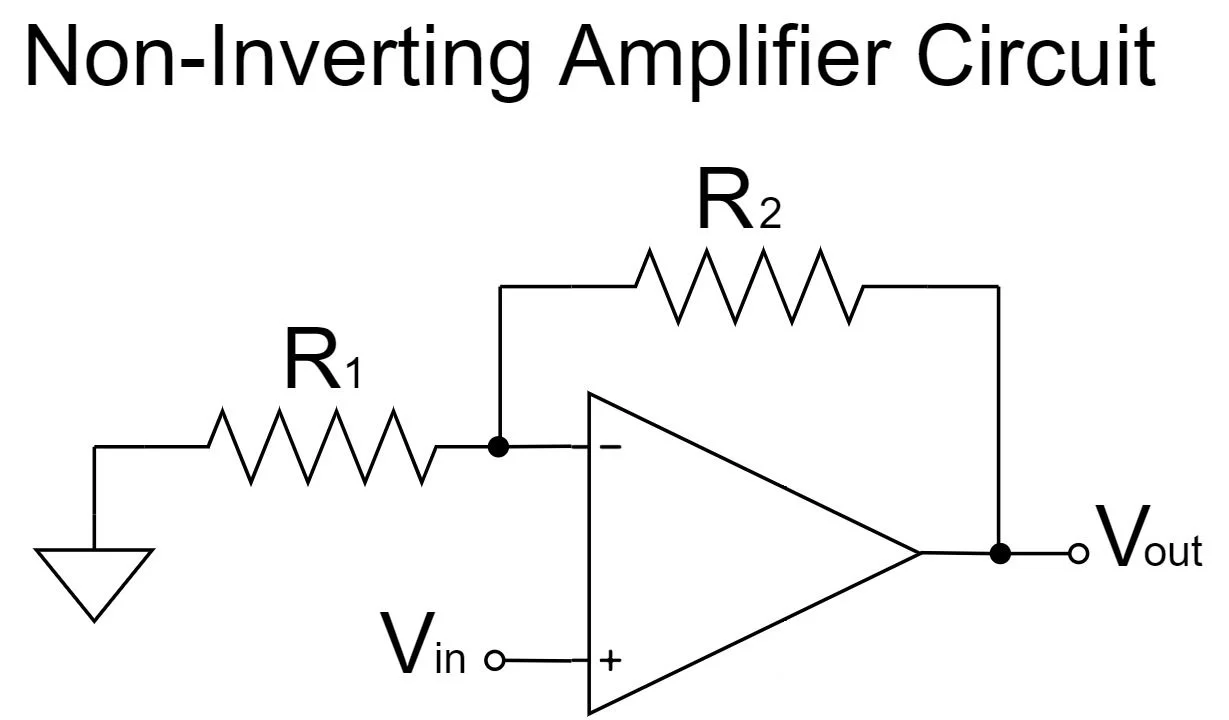
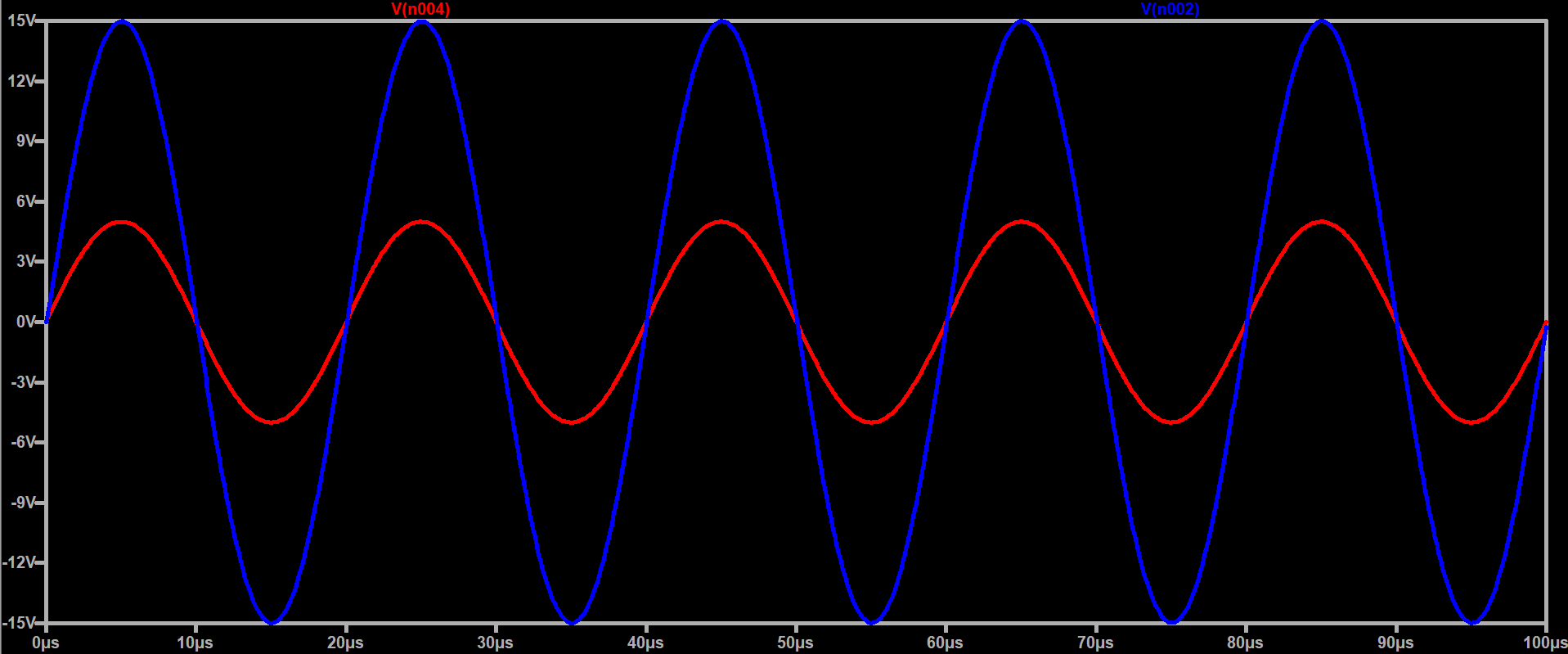
A non-inverting amplifier is one of the most common op-amp circuits used to boost a signal's voltage without flipping its polarity — meaning the output waveform stays perfectly in phase with the input. In this article, we'll break down how it works, derive the gain formula, and walk through a real simulation in LTspice where a 5V signal is amplified to 15V.
What Is a Non-Inverting Amplifier?
In a non-inverting amplifier, the input signal is applied directly to the op-amp's non-inverting (+) terminal, while a voltage divider made of two resistors (R1 and R2) feeds a portion of the output back into the inverting (-) terminal. This creates negative feedback, which stabilizes the gain and keeps the output in phase with the input.
The Gain Formula
The closed-loop gain of a non-inverting amplifier is given by:
Av = 1 + (R2 / R1)
Where:
- R2 is the feedback resistor (connected between the output and the inverting input)
- R1 is the resistor connected between the inverting input and ground
Worked Example: 5V In, 15V Out
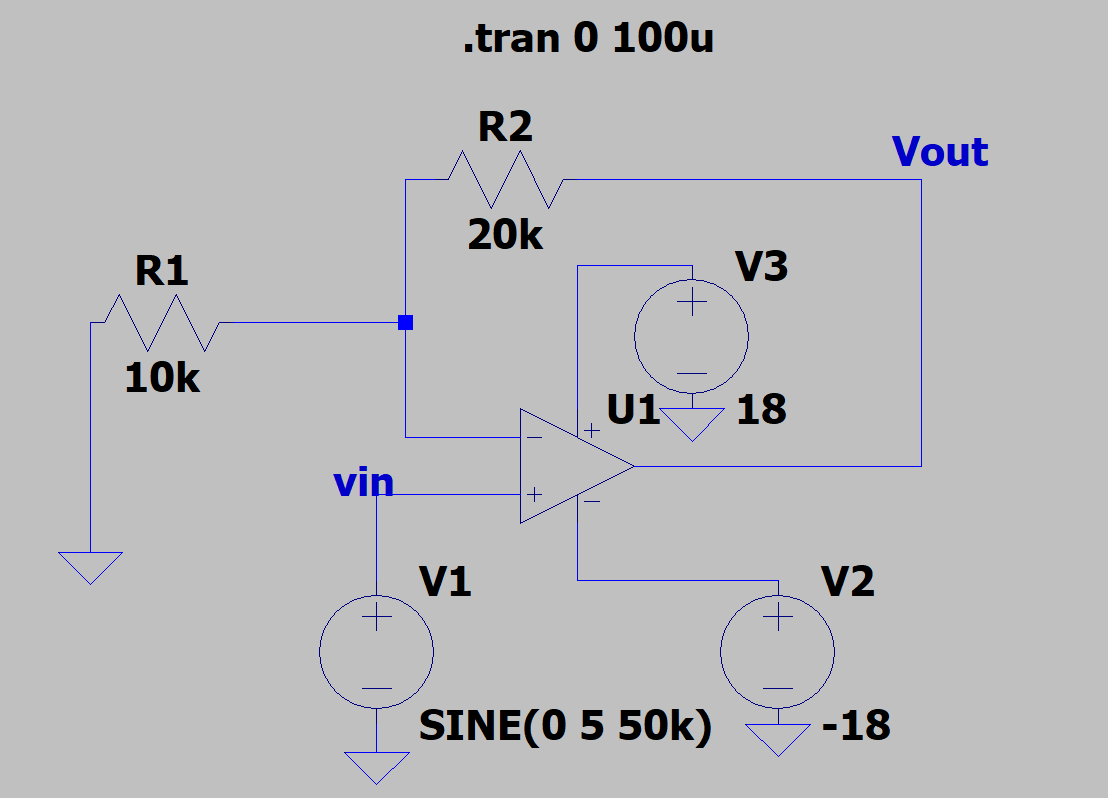
Using the LTspice circuit above, R1 = 10kΩ and R2 = 20kΩ. Plugging these into the formula:
Av = 1 + (20k / 10k) = 1 + 2 = 3
The input source is a 5V peak sine wave at 50kHz with no DC offset — SINE(0 5 50k). Since the gain is 3, the output becomes:
Vout = Av × Vin = 3 × 5V = 15V peak
The op-amp is powered from a ±18V dual supply (V3 = +18V, V2 = -18V), which gives enough headroom so the 15V peak output never clips against the rails.
Why There's No DC Offset
Because R1 connects straight to ground and the input signal itself has zero DC component, there's no DC bias introduced into the circuit. The output waveform is simply the input scaled by the gain and stays centered on 0V, just like the simulation confirms.
Key Takeaways
- Non-inverting amplifiers keep the output in phase with the input.
- Gain is always ≥ 1, calculated as 1 + (R2/R1).
- A dual supply (like ±18V here) allows the output to swing both positive and negative without clipping.
- With no DC offset at the input and R1 tied to ground, the output stays centered at 0V.
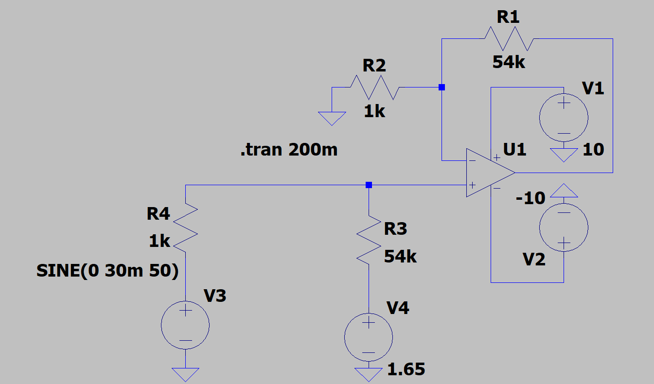 Non-Inverting Amplifier Explained: 30mV to 3.3V Gain and Offset Example