 1 / 3
1 / 3
Project Overview
Firmware Architecture, Controller Logic & Hardware Interconnections
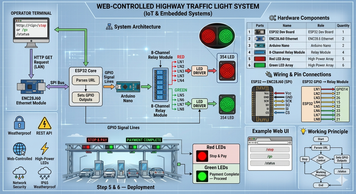
The complete toll signaling system is built around a dual-controller architecture utilizing an ESP32 Ethernet Controller and an Arduino Nano Output Controller. The ESP32 manages all network communication, web-server functionality, relay switching commands, and remote traffic signal requests, while the Arduino Nano acts as a dedicated low-level controller responsible for LED driver activation and traffic light state enforcement.
Separating networking functions from power-switching logic increases system stability, improves fault tolerance, simplifies troubleshooting, and ensures that high-current LED driver operations remain isolated from Ethernet communication processes.
ESP32 Ethernet Controller
The ESP32 hosts an embedded HTTP server using the UIPEthernet library and the ENC28J60 Ethernet interface. Through simple URL commands, an operator can remotely switch between STOP and GO traffic states over a wired LAN connection.
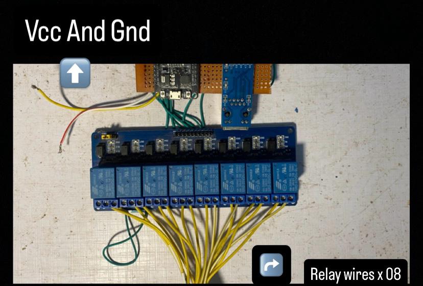
| ESP32 GPIO | Relay Channel | Purpose |
|---|---|---|
| GPIO14 | Relay 1 | Traffic Control Output |
| GPIO27 | Relay 2 | Traffic Control Output |
| GPIO26 | Relay 3 | Traffic Control Output |
| GPIO13 | Relay 4 | Traffic Control Output |
| GPIO32 | Relay 5 | Traffic Control Output |
| GPIO33 | Relay 6 | Traffic Control Output |
| GPIO25 | Relay 7 | Traffic Control Output |
| GPIO21 | Relay 8 | Traffic Control Output |
ENC28J60 Ethernet Module Connections
| ENC28J60 Pin | ESP32 Pin | Function |
|---|---|---|
| VCC | 3.3V | Power Supply |
| GND | GND | Common Ground |
| SCK | GPIO18 | SPI Clock |
| SO (MISO) | GPIO19 | SPI Data Receive |
| SI (MOSI) | GPIO23 | SPI Data Transmit |
| CS | GPIO5 | Chip Select |
ESP32 Firmware Features
- Embedded HTTP server running on Port 80.
- Remote URL-based traffic control.
- Static IP configuration using Ethernet.
- Persistent configuration storage using Preferences library.
- Automatic relay state management.
- Remote traffic light switching through browser requests.
- LAN deployment without Wi-Fi dependency.
- Industrial-grade wired communication for toll environments.
GET http://device-ip/go
→ Green Traffic Signal Activated

GET http://device-ip/stop
→ Red Traffic Signal Activated

GET http://device-ip/status
→ Current System Status
Arduino Nano Traffic Signal Controller
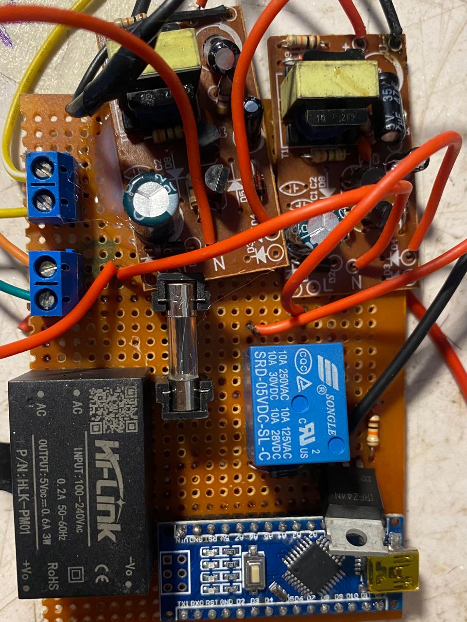
The Arduino Nano receives the relay state generated by the ESP32 system and translates that state into actual LED driver commands. MOSFET outputs are used because the LED arrays require significantly higher current than a microcontroller GPIO can safely provide.
| Arduino Pin | Connected Device | Function |
|---|---|---|
| D2 | Relay Output from ESP32 | Traffic State Input |
| D3 | Green MOSFET Gate | Green LED Driver Enable |
| D4 | Red MOSFET Gate | Red LED Driver Enable |
Firmware Decision Logic
- Operator accesses /go URL.
- ESP32 processes HTTP request.
- Relay output becomes HIGH.
- Arduino reads HIGH on D2.
- D3 MOSFET enabled.
- Green LED Driver activated.
- 354 Green LEDs illuminate.
- Vehicles proceed through toll lane.
- Operator accesses /stop URL.
- ESP32 processes HTTP request.
- Relay output becomes LOW.
- Arduino reads LOW on D2.
- D4 MOSFET enabled.
- Red LED Driver activated.
- 354 Red LEDs illuminate.
- Vehicles remain stopped for payment.
Controller Source Code Summary
Uses UIPEthernet, Preferences, EthernetServer, static IP configuration, relay GPIO mapping, HTTP route parsing and persistent storage. The controller listens for browser requests and immediately updates relay outputs connected to the traffic signaling subsystem.
Arduino Nano FirmwareContinuously monitors the relay signal on D2. When HIGH, D3 activates the Green MOSFET while D4 remains disabled. When LOW, D4 activates the Red MOSFET while D3 remains disabled. This guarantees mutually exclusive traffic states.
The firmware architecture ensures that red and green LED arrays can never be energized simultaneously. This interlocked design eliminates conflicting traffic indications and guarantees safe toll booth operation even during repeated network requests or rapid state changes.
Tech Stack
Tags
| Controller | ESP32 Wi-Fi Microcontroller |
| Secondary Controller | Arduino Nano |
| Programming Language | C/C++ (Arduino IDE) |
| Communication Interface | Digital GPIO Signaling |
| Traffic Indicators | High-Power Red & Green LED Arrays |
| Switching Device | N-Channel MOSFET Drivers |
| Relay Module | 5V SPDT Relay Interface |
| Vehicle Detection | IR Sensor Module |
| Network Connectivity | Wi-Fi (ESP32) |
| Response Time | < 100 ms |
| Input Voltage | 5V DC |
| Logic Voltage | 3.3V / 5V Compatible |
| Automation Logic | Sensor-Based Vehicle Detection |
| Display Status | Red (STOP) / Green (GO) |
| Embedded Platform | Arduino Nano + ESP32 |
| Development Environment | Arduino IDE |
| Safety Feature | Interlocked Traffic Signal Control |
| Power Management | Relay-Isolated LED Driver Switching |
| Application Domain | Smart Toll Collection & Traffic Automation |