 1 / 4
1 / 4
Project Overview
ECG Front-End Design: Low-Noise Amplification & Signal Acquisition
This project focuses on the design and implementation of an ECG (Electrocardiogram) front-end system capable of acquiring extremely weak bio-potential signals from the human body and converting them into a clean, observable waveform. The system demonstrates the complete signal processing chain from biological acquisition to real-time digital visualization.
ECG signals are exceptionally small (typically 0.05 mV – 5 mV) and easily buried under muscle activity (EMG), power line hum, motion artifacts, and baseline drift. Precise analog filtering and high-gain amplification are mandatory.
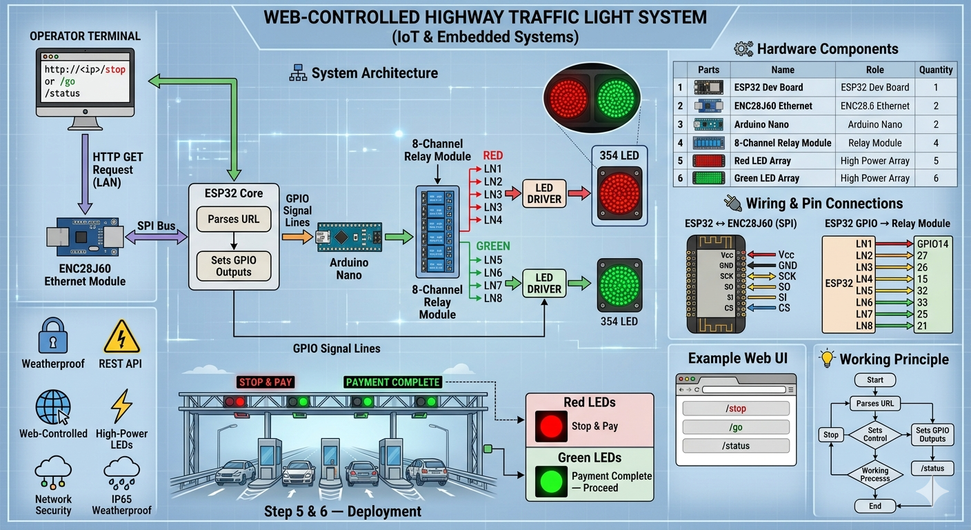
System Signal Chain
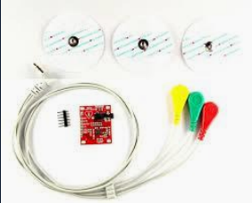
- Signal Acquisition: Silver–Chloride (Ag/AgCl) electrodes convert ionic body currents into electrical signals using standard RA, LA, and RL (Ground) placement.
- Precision Amplification: An Instrumentation Amplifier provides a high Common Mode Rejection Ratio (CMRR) to systematically reject noise present on both input leads.
- Real-Time Display: An Arduino Nano microprocessor captures the analog output via ADC and plots the continuous waveform on a high-contrast 0.96" I2C OLED matrix.
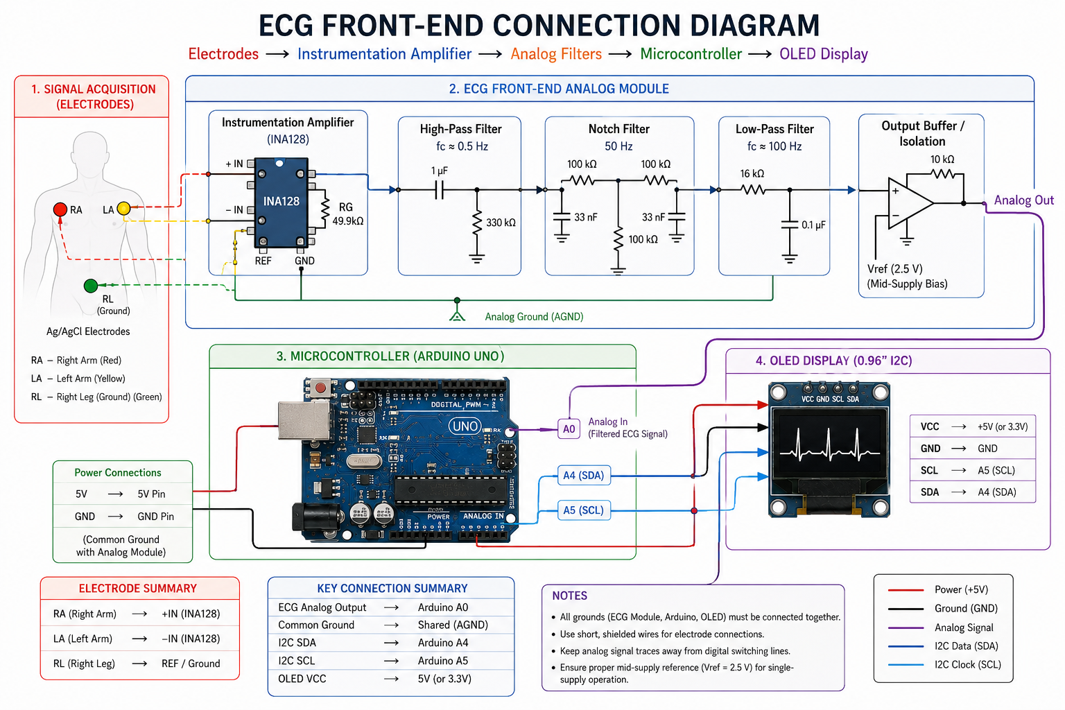
Analog Conditioning & Design Parameters
| Circuit Stage | Component Specifications | Target / Purpose |
|---|---|---|
| Instrumentation Amp | Gain Resistor RG = 49.9 kΩ | Differential microvolt scaling |
| High-Pass Filter | R = 330 kΩ, C = 1 µF (fc ≈ 0.5 Hz) | Removes breathing & baseline drift noise |
| Hardware Notch Filter | Narrowband Attenuation at 50 Hz | Eliminates main power line hum |
| Low-Pass Filter | R = 16 kΩ, C = 0.1 µF (fc ≈ 100 Hz) | Suppresses high-frequency EMG muscle noise |
| Output Isolation | 10 kΩ Buffer & Reference Bias Networks | Ensures unity gain & safe patient reference |
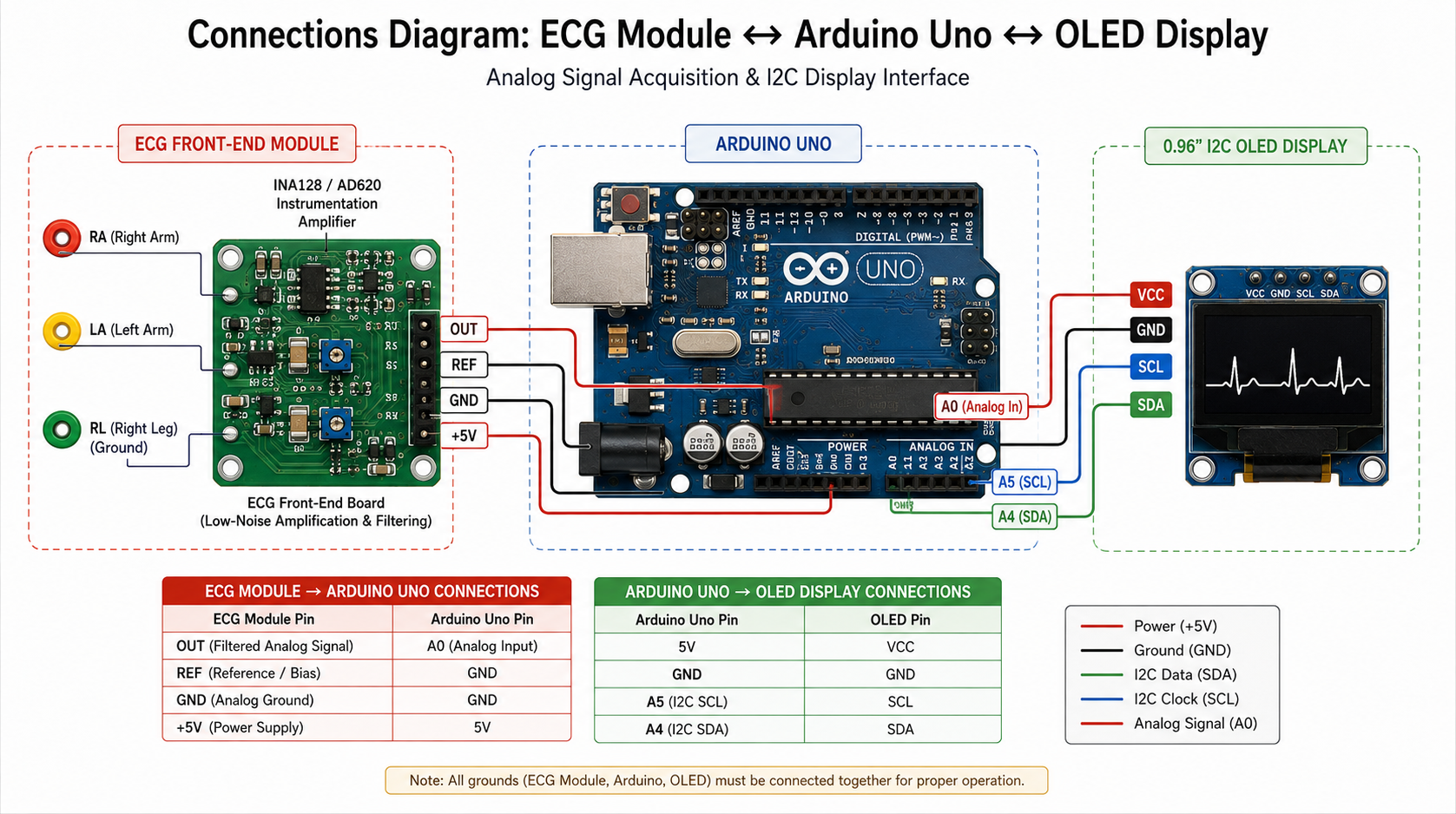
Hardware Interface & Pin Configuration
| Subsystem Module Component | Hardware Pin Assignment | Arduino Nano Connection Point |
|---|---|---|
| ECG Circuit Signal Output | Analog Out (Filtered Signal) | A0 (Analog Input Pin) |
| ECG Analog Ground Reference | GND (Reference Bias Common) | GND |
| I2C OLED Display Panel | SDA (Serial Data Line) | A4 (Hardware I2C SDA) |
| I2C OLED Display Panel | SCL (Serial Clock Line) | A5 (Hardware I2C SCL) |
| OLED VCC Power Rail | VCC (+5V Power) | +5V (or 3.3V depending on display) |
| OLED Ground Link | GND (Common Return) | GND |
Arduino Nano Firmware (Waveform Rendering)
#include <Wire.h>
#include <Adafruit_GFX.h>
#include <Adafruit_SSD1306.h>

#define SCREEN_WIDTH 128 // OLED display width, in pixels
#define SCREEN_HEIGHT 64 // OLED display height, in pixels
#define OLED_RESET    -1 // Share reset pin with Arduino
Adafruit_SSD1306 display(SCREEN_WIDTH, SCREEN_HEIGHT, &Wire, OLED_RESET);

const int ecgPin = A0;   // Analog input connection from front-end
int xPos = 0;            // Horizontal chart coordinate
int lastY = 32;          // Track previous sample height

void setup() {
  Serial.begin(115200);

  // Initialize SSD1306 display panel over I2C at address 0x3C
  if(!display.begin(SSD1306_SWITCHCAPVCC, 0x3C)) {
    Serial.println(F("OLED Allocation Failed"));
    for(;;);
  }

  display.clearDisplay();
  display.setTextSize(1);
  display.setTextColor(SSD1306_WHITE);
  display.setCursor(15, 24);
  display.println(F("ECG FRONT-END READY"));
  display.display();
  delay(1500);
  display.clearDisplay();
}

void loop() {
  // Read raw biometric signal from data pipeline
  int rawAnalog = analogRead(ecgPin);

  // Map the 10-bit input value (0-1023) down into OLED screen height limits (0-63)
  int yPos = map(rawAnalog, 0, 1023, SCREEN_HEIGHT - 5, 5);

  // Render continuous signal tracking bars dynamically
  if (xPos > 0) {
    display.drawLine(xPos - 1, lastY, xPos, yPos, SSD1306_WHITE);
  }

  lastY = yPos;
  xPos++;

  // Sweep screen edge constraint loop reset
  if (xPos >= SCREEN_WIDTH) {
    xPos = 0;
    display.clearDisplay();
  }

  display.display();
  delay(10); // Enforces proper sampling constraints
}
Conclusion & Applications
The completed ECG front-end device cleanly validates how micro-level bio-potentials can be isolated safely, amplified linearly, and tracked dynamically. By enforcing rigid analog hardware boundaries alongside an isolated embedded module, the platform serves as a reliable building block for portable healthcare monitoring equipment and research laboratory data acquisition devices.
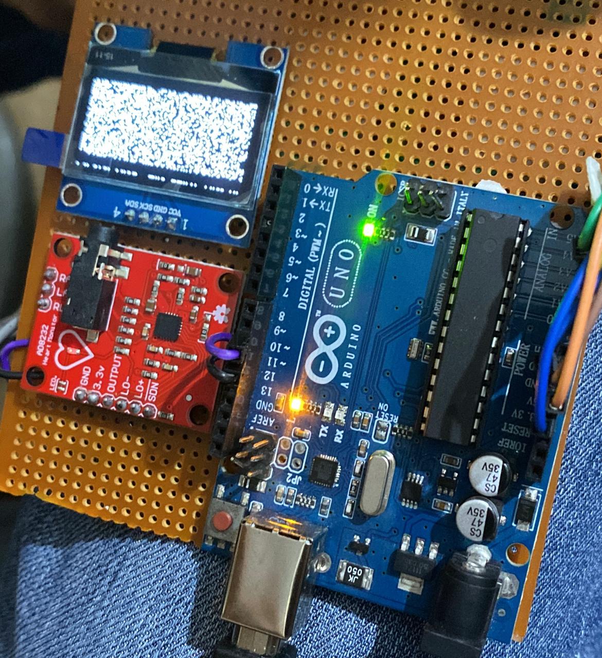
Hardware Connections
Technical Specifications
Instrumentation Amplifier: INA128 / AD620
High-Pass Filter Cutoff: ≈ 0.5 Hz
Notch Filter Frequency: 50 Hz
Low-Pass Filter Cutoff: ≈ 100 Hz
Microcontroller: Arduino Uno (ATmega328P)
ADC Resolution: 10-bit
Analog Input: A0
Display Type: 0.96" OLED (128×64)
Communication Interface: I²C
SDA Pin: A4
SCL Pin: A5
Operating Voltage: 5V DC
Signal Visualization: Real-Time ECG Waveform
All grounds (ECG Module, Arduino Uno, and OLED Display) must share a common reference point. Proper grounding minimizes noise, improves signal integrity, and ensures stable ECG waveform acquisition.
Tech Stack
Tags
| ECG Signal Range | 0.05 mV – 5 mV |
| Instrumentation Amplifier | INA128 / AD620 |
| Amplifier Gain | Configurable via External Gain Resistor (RG) |
| Input Configuration | Differential (RA, LA) |
| Reference Electrode | RL (Right Leg) |
| High-Pass Filter Cutoff | ≈ 0.5 Hz |
| Notch Filter Frequency | 50 Hz |
| Low-Pass Filter Cutoff | ≈ 100 Hz |
| Microcontroller | Arduino Uno (ATmega328P) |
| ADC Resolution | 10-bit |
| Analog Input Channel | A0 |
| Display Type | 0.96" OLED Display |
| Display Interface | I²C |
| OLED Resolution | 128 × 64 Pixels |
| I²C SDA Pin | A4 |
| I²C SCL Pin | A5 |
| Operating Voltage | 5 V DC |
| Power Consumption | < 100 mA (Typical) |
| Sampling Method | Real-Time Analog Acquisition |
| Grounding Scheme | Common Ground (ECG, Arduino, OLED) |
| Signal Output | Filtered Analog ECG Waveform |
| Application | ECG Monitoring & Biomedical Signal Acquisition |