Precision Peak Detector: Simulating an Audio Envelope Follower in LTspice
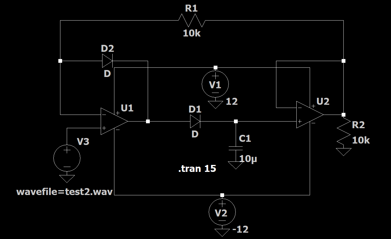
A peak detector does exactly what it sounds like — it grabs the highest point of a signal and holds onto it. Feed it a messy, jumpy waveform like an audio track, and it hands you back a clean, stepped line tracing every peak. That's the circuit we're building and simulating here, using a real two-op-amp precision peak detector in LTspice, driven by an actual .wav audio file instead of a plain sine wave.
What a Peak Detector Actually Does
A basic diode-and-capacitor peak detector works fine at high signal levels, but it struggles with small voltages because the diode's forward drop eats into the signal before it ever reaches the capacitor. The fix is to put the diode inside an op-amp's feedback loop. The op-amp's open-loop gain forces the diode to conduct with almost no error, so the capacitor charges to the true peak voltage — not the peak minus a diode drop.
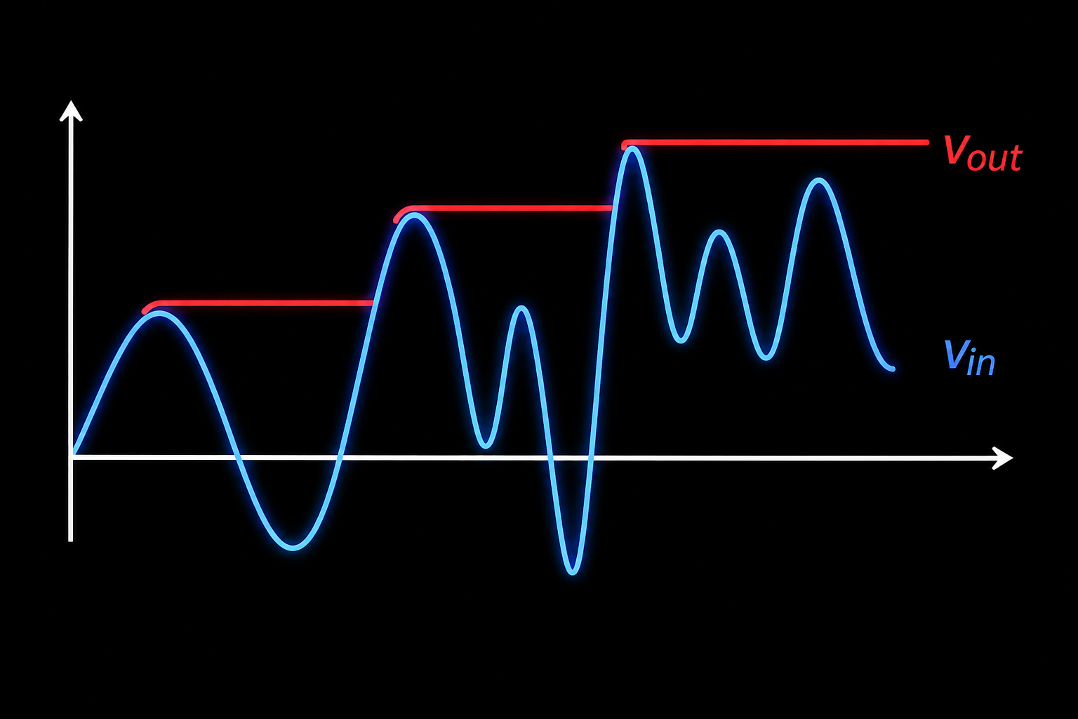
The diagram above is the concept in its simplest form: as Vin rises and falls, Vout only ever moves upward, stepping to match each new peak and holding steady until a taller peak comes along.
Circuit Breakdown
The schematic uses two op-amps, two diodes, and a hold capacitor:
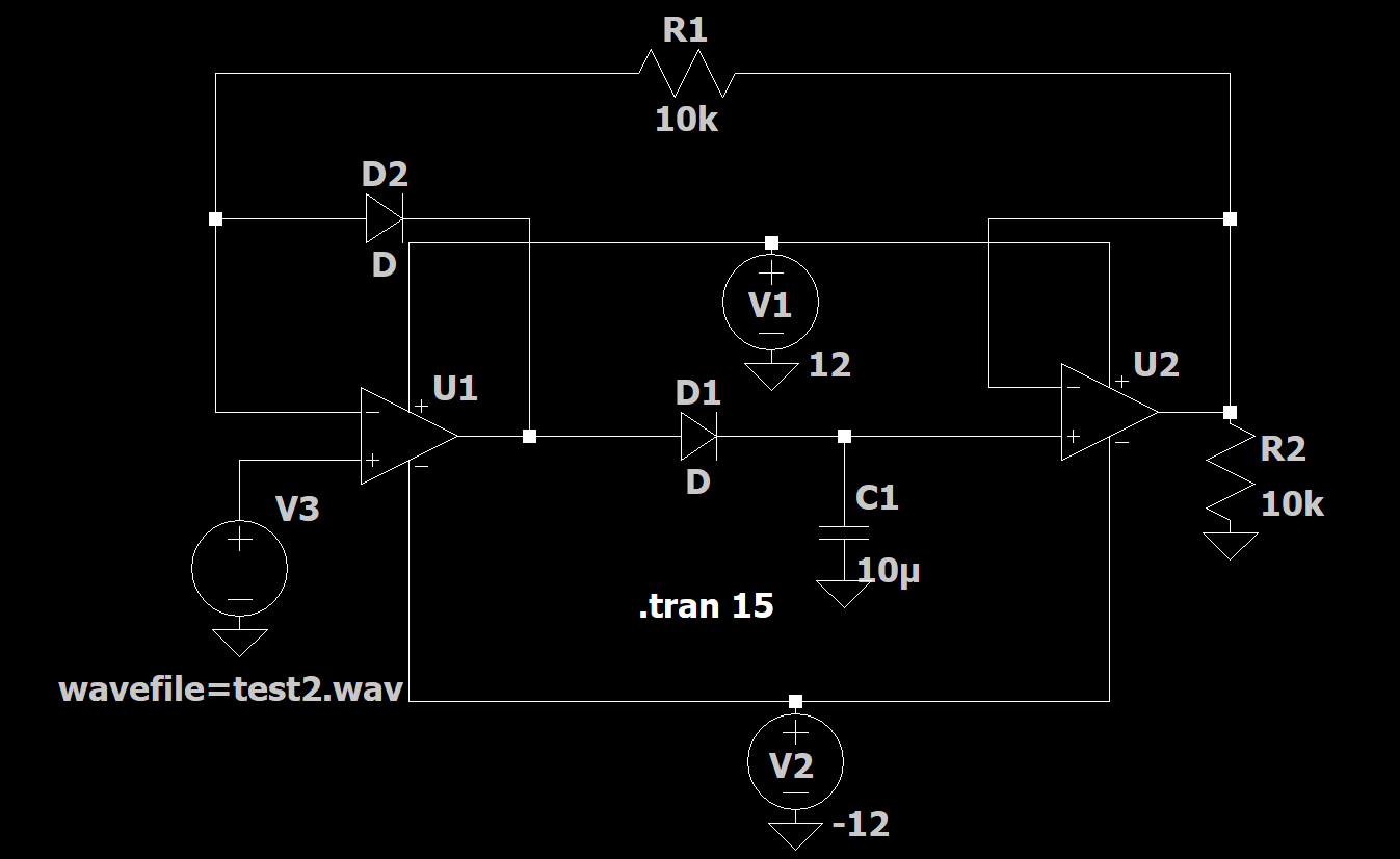
- U1 (comparator stage): Compares the incoming audio (V3, sourced from a .wav file) against the held output voltage.
- D1 + C1 (10µF): When U1's output swings high, D1 conducts and charges the hold capacitor to the new peak almost instantly.
- D2 + R1 (10k): This feedback path keeps U1 from railing out and slamming into saturation when the input drops — without it, the circuit would take too long to "wake up" for the next peak, a classic peak detector slew problem.
- U2 (buffer stage): Isolates the capacitor from R2 (10k) so the load doesn't discharge the stored peak, giving a clean, low-impedance Vout.
- V1 / V2 (±12V): Supply rails for both op-amps.
Feeding It Real Audio in LTspice
Instead of a sine or triangle wave, this simulation uses a real .wav file as the input source — a good way to stress-test the circuit against a signal with unpredictable, fast-changing peaks, closer to what the circuit would see in a real audio application like a VU meter or compressor sidechain.

To set this up yourself:
- Place a standard voltage source in LTspice.
- Hold Ctrl and right-click the source symbol to open the Component Attribute Editor.
- In the Value field, type
wavefile=yourfilename.wav— swap in your actual file name. - Click OK, then run a transient simulation (here,
.tran 15for a 15-second run).
Important: keep the .wav file in the same folder as your .asc schematic file, or LTspice won't find it.
The Result
Run the simulation and overlay Vin against Vout, and the peak-tracking behavior is obvious — the red trace climbs in clean steps, locking onto each new high point in the audio while ignoring everything below it.
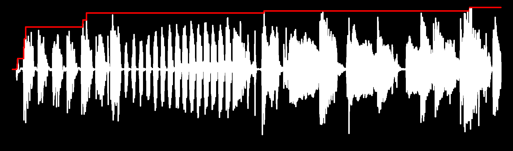
Notice how the output only ever steps upward within this window — that's expected for a positive peak-hold detector with no reset or decay path. In a real audio application you'd typically add a bleed resistor across C1 to let the voltage decay slowly between peaks, turning this into an envelope follower rather than a pure peak-and-hold.
Where This Circuit Is Used
Precision peak detectors like this one show up in audio level meters, AGC (automatic gain control) circuits, envelope followers for synthesizers, and RF signal strength measurement — anywhere you need to capture and hold the highest point of a fast-moving signal without losing accuracy to diode drop errors.